


- HOME
- >
- NEWS
| The examples and perspective in this article may not represent a worldwide view of the subject. (May 2011) |

Numerical control (NC) is the automation of machine tools that are operated by abstractly programmed commands encoded on a storage medium, as opposed to controlled manually via handwheels or levers, or mechanically automated via cams alone. Most NC today is computer numerical control (CNC), in which computers play an integral part of the control.
In modern CNC systems, end-to-end component design is highly automated using computer-aided design (CAD) and computer-aided manufacturing (CAM) programs. The programs produce a computer file that is interpreted to extract the commands needed to operate a particular machine via a postprocessor, and then loaded into the CNC machines for production. Since any particular component might require the use of a number of different tools – drills, saws, etc., modern machines often combine multiple tools into a single "cell". In other cases, a number of different machines are used with an external controller and human or robotic operators that move the component from machine to machine. In either case, the complex series of steps needed to produce any part is highly automated and produces a part that closely matches the original CAD design.
Contents
[hide]History[edit source | edit]
The first NC machines were built in the 1940s and 1950s, based on existing tools that were modified with motors that moved the controls to follow points fed into the system on punched tape. These early servomechanisms were rapidly augmented with analog and digital computers, creating the modern CNC machine tools that have revolutionized the machining processes.
Description[edit source | edit]
Modern CNC mills differ little in concept from the original model built at MIT in 1952. Mills typically consist of a table that moves in the X and Y axes, and a tool spindle that moves in the Z (depth). The position of the tool is driven by motors through a series of step-down gears in order to provide highly accurate movements, or in modern designs, direct-drive stepper motor or servo motors. Open-loop control works as long as the forces are kept small enough and speeds are not too great. On commercial metalworking machines closed loop controls are standard and required in order to provide the accuracy, speed, and repeatability demanded.
As the controller hardware evolved, the mills themselves also evolved. One change has been to enclose the entire mechanism in a large box as a safety measure, often with additional safety interlocks to ensure the operator is far enough from the working piece for safe operation. Most new CNC systems built today are completely electronically controlled.
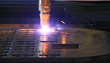
CNC-like systems are now used for any process that can be described as a series of movements and operations. These include laser cutting, welding, friction stir welding, ultrasonic welding, flame and plasma cutting, bending, spinning, hole-punching, pinning, gluing, fabric cutting, sewing, tape and fiber placement, routing, picking and placing (PnP), and sawing.
Tools with CNC variants[edit source | edit]
- Drills
- EDMs
- Embroidery machines
- Lathes
- Milling machines
- Wood routers
- Sheet metal works (Turret Punch)
- Wire bending machines
- Hot-wire foam cutters
- Plasma cutters
- Water jet cutters
- Laser cutting
- Oxy-fuel
- Surface grinders
- Cylindrical grinders
- 3D Printing
- Induction hardening machines[citation needed]
- submerged welding
- knife cutting
- glass cutting
Tool / machine crashing[edit source | edit]
In CNC, a "crash" occurs when the machine moves in such a way that is harmful to the machine, tools, or parts being machined, sometimes resulting in bending or breakage of cutting tools, accessory clamps, vices, and fixtures, or causing damage to the machine itself by bending guide rails, breaking drive screws, or causing structural components to crack or deform under strain. A mild crash may not damage the machine or tools, but may damage the part being machined so that it must be scrapped.
Many CNC tools have no inherent sense of the absolute position of the table or tools when turned on. They must be manually "homed" or "zeroed" to have any reference to work from, and these limits are just for figuring out the location of the part to work with it, and aren't really any sort of hard motion limit on the mechanism. It is often possible to drive the machine outside the physical bounds of its drive mechanism, resulting in a collision with itself or damage to the drive mechanism. Many machines implement control parameters limiting axis motion past a certain limit in addition to physical limit switches. However, these parameters can often be changed by the operator.
Many CNC tools also don't know anything about their working environment. Machines may have load sensing systems on spindle and axis drives, but some do not. They blindly follow the machining code provided and it is up to an operator to detect if a crash is either occurring or about to occur, and for the operator to manually abort the cutting process. Machines equipped with load sensors can stop axis or spindle movement in response to an overload condition, but this does not prevent a crash from occurring. It may only limit the damage resulting from the crash. Some crashes may not ever overload any axis or spindle drives.
If the drive system is weaker than the machine structural integrity, then the drive system simply pushes against the obstruction and the drive motors "slip in place". The machine tool may not detect the collision or the slipping, so for example the tool should now be at 210mm on the X axis but is in fact at 32mm where it hit the obstruction and kept slipping. All of the next tool motions will be off by −178mm on the X axis, and all future motions are now invalid, which may result in further collisions with clamps, vises, or the machine itself. This is common in open loop stepper systems, but is not possible in closed loop systems unless mechanical slippage between the motor and drive mechanism has occurred. Instead, in a closed loop system, the machine will continue to attempt to move against the load until either the drive motor goes into an overcurrent condition or a servo following error alarm is generated.
Collision detection and avoidance is possible, through the use of absolute position sensors (optical encoder strips or disks) to verify that motion occurred, or torque sensors or power-draw sensors on the drive system to detect abnormal strain when the machine should just be moving and not cutting, but these are not a common component of most hobby CNC tools.
Instead, most hobby CNC tools simply rely on the assumed accuracy of stepper motors that rotate a specific number of degrees in response to magnetic field changes. It is often assumed the stepper is perfectly accurate and never mis-steps, so tool position monitoring simply involves counting the number of pulses sent to the stepper over time. An alternate means of stepper position monitoring is usually not available, so crash or slip detection is not possible.
Commercial CNC metalworking machines use closed loop feedback controls for axis movement. In a closed loop system, the control is aware of the actual position of the axis at all times. With proper control programming, this will reduce the possibility of a crash, but it is still up to the operator and tool path programmer to ensure that the machine is operated in a safe manner.
Numerical accuracy vs Equipment backlash[edit source | edit]
Within the numerical systems of CNC programming it is possible for the code generator to assume that the controlled mechanism is always perfectly accurate, or that accuracy tolerances are identical for all cutting or movement directions. This is not always a true condition of CNC tools. CNC tools with a large amount of mechanical backlash can still be highly accurate if the drive or cutting mechanism is only driven so as to apply cutting force from one direction, and all driving systems are pressed tight together in that one cutting direction. However a CNC device with high backlash and a dull cutting tool can lead to cutter chatter and possible workpiece gouging. Backlash also affects accuracy of some operations involving axis movement reversals during cutting, such as the milling of a circle, where axis motion is sinusoidal. However, this can be compensated for if the amount of backlash is precisely known by linear encoders or manual measurement.
The high backlash mechanism itself is not necessarily relied on to be repeatedly accurate for the cutting process, but some other reference object or precision surface may be used to zero the mechanism, by tightly applying pressure against the reference and setting that as the zero reference for all following CNC-encoded motions. This is similar to the manual machine tool method of clamping a micrometer onto a reference beam and adjusting the Vernier dial to zero using that object as the reference.
TEL:+886-4-26269306~7 FAX:+886-4-26269308 E-mail:info@twt-global.com